Please note: This article is a work in progress and may not contain complete information.
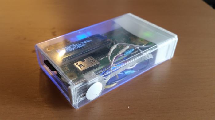
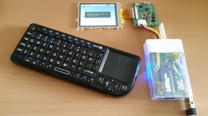
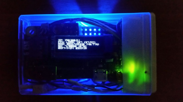
This is my latest design for a Pi-powered Tic-Tac box that can be used as a WiFi access point, Pi-Hole server, piratebox, etc. The guide assumes you have a basic understanding of Linux, soldering, and electronic components. The project incorporates the following parts:
Important: This guide was prepared using Raspbian Stretch and may not work on older or newer versions of Raspbian
- 1x Raspberry Pi Zero W
- 1x micro SD card with Raspbian installed (8GB minimum, 16GB recommended)
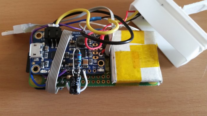
- 1x Adafruit Powerboost 1000C
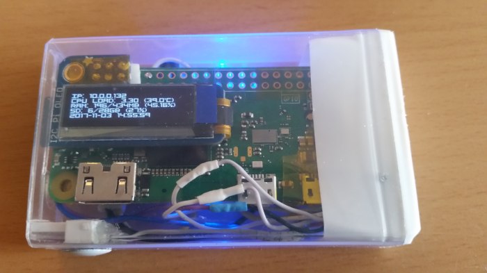
- 1x Adafruit PiOLED
- 1x 285mAh Lithium Polymer battery with JST connector (higher capacity batteries cam be used but the dimensions must be approximately 2.5cm x 2.5cm)
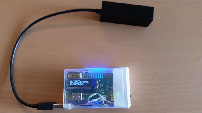
- 1x USB female type A port
- 2x momentary buttons
- 1x SPST (Single-Pole Single-Throw), or SPDT (Single-Pole Double-Throw) switch
- 1x standard small Tic-Tac box
- 1x 100uf electrolytic capacitor
- 1x 10K resistor
- 1x 100K resistor
- Various wires, hot glue, polyimide tape, double-sided tape, thumbtack, heat-shrink tubing, solder, and flux (I’ve found that strips of old IDE ribbon cables are great for miniature projects like this, as long as they’re carefully stripped, tinned, and soldered)
The following guides were used:
- Installing Raspbian on a micro SD card using NOOBS
- Connecting the Adafruit Powerboost 1000C for safe shutdown (lipopi)
- Adafruit PiOLED stats example
- Add a safe off-switch to power down your Raspberry Pi
- Setting up a Raspberry Pi as an access point in a standalone network
Guide modifications:
- The newer Powerboost 1000Cs appear to have a different pinout than the one in the photos. Be sure to connect the wires and components according to the labels, and NOT their relative positions on the PCB.
- The Powerboost 1000C will also need to be modified according to the image description below.
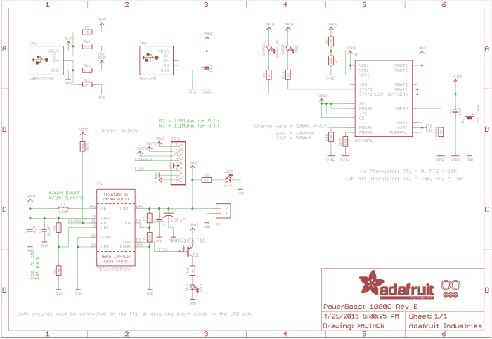
- As mentioned in the lipopi tutorial, the Pi Zero W uses emulated UART similar to the Pi 3, so the option to send a login prompt over serial should be turned off, but the serial port should be left enabled. This can be done by opening a terminal interface, typing sudo raspi-config, selecting Interfacing Options, then Serial, and following the prompts. This is done to ensure that GPIO 14 remains high after the Powerboost has powered the Pi Zero W. Furthermore, a 100uf capacitor must be placed across the 100K resistor to ensure that the signal remains stable enough to keep the Powerboost from shutting down. Capacitors are polarity-sensitive, so be sure to align the positive and negative leads properly.
- Carefully desolder the female header from the Adafruit PiOLED and connect it to the Pi using a strip of IDE ribbon cable. Be very careful, since the corners of the glass display are very fragile.
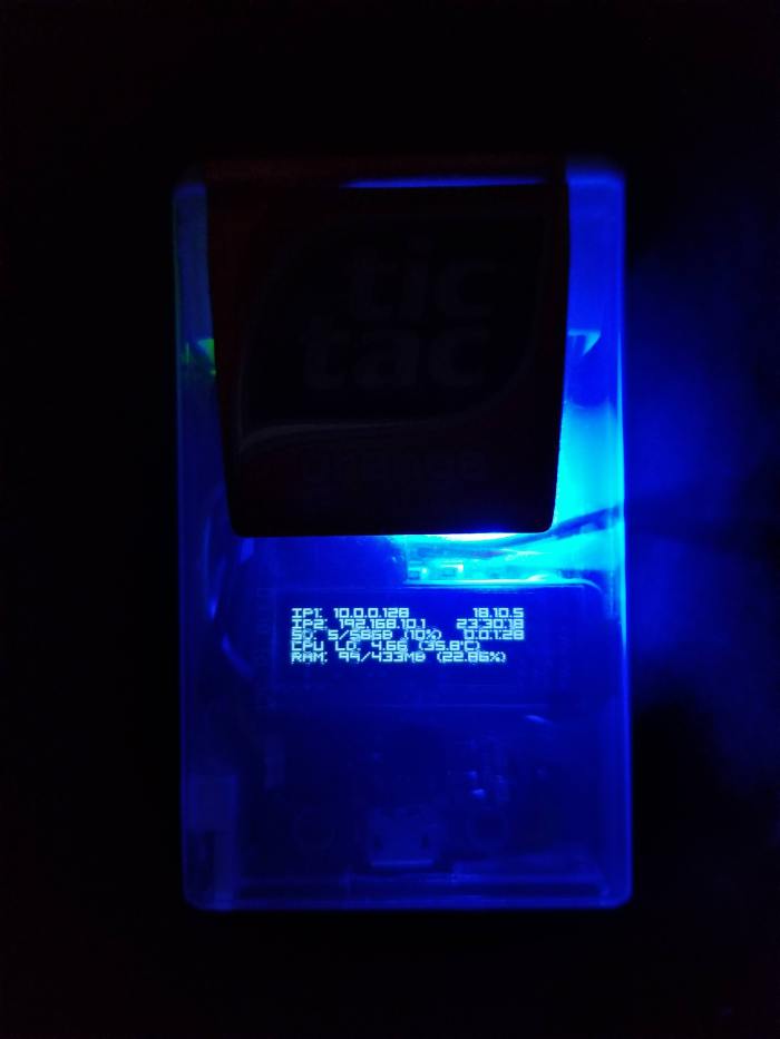
- The following changes were made to the stats.py script to add a temperature indicator, date and time, increase readability, and maximize the amount of information that could be displayed on the screen:
– Download the visitor1.ttf font here, and place it in the same folder as the stats.py script
– Add the line import os near the other imports around lines 22-30
– Finally, replace the following section of code
 # Load default font.
 font = ImageFont.load_default()

 # Alternatively load a TTF font.
 # Some other nice fonts to try: http://www.dafont.com/bitmap.php
 #font = ImageFont.truetype('Minecraftia.ttf', 8)

 while True:

 # Draw a black filled box to clear the image.
 draw.rectangle((0,0,width,height), outline=0, fill=0)

 # Shell scripts for system monitoring from here : https://unix.stackexchange.com/questions/119126/command-to-display-memory-usage-disk-usage-and-cpu-load
 cmd = "hostname -I | cut -d\' \' -f1"
 IP = subprocess.check_output(cmd, shell = True )
 cmd = "top -bn1 | grep load | awk '{printf \"CPU Load: %.2f\", $(NF-2)}'"
 CPU = subprocess.check_output(cmd, shell = True )
 cmd = "free -m | awk 'NR==2{printf \"Mem: %s/%sMB %.2f%%\", $3,$2,$3*100/$2 }'"
 MemUsage = subprocess.check_output(cmd, shell = True )
 cmd = "df -h | awk '$NF==\"/\"{printf \"Disk: %d/%dGB %s\", $3,$2,$5}'"
 Disk = subprocess.check_output(cmd, shell = True )

 # Write two lines of text.

 draw.text((x, top), "IP: " + str(IP), font=font, fill=255)
 draw.text((x, top+8), str(CPU), font=font, fill=255)
 draw.text((x, top+16), str(MemUsage), font=font, fill=255)
 draw.text((x, top+25), str(Disk), font=font, fill=255)

 # Display image.
 disp.image(image)
 disp.display()
 time.sleep(.1)
with
 # Load default font.
#font = ImageFont.load_default()
#font = ImageFont.truetype('visitor2.ttf', 8)

# Alternatively load a TTF font. Make sure the .ttf font file is in the same directory as the python script!
# Some other nice fonts to try: http://www.dafont.com/bitmap.php
font = ImageFont.truetype('/home/pi/Adafruit_Python_SSD1306/examples/visitor1.ttf', 10)

while True:

	# Draw a black filled box to clear the image.
	draw.rectangle((0,0,width,height), outline=0, fill=0)

	# Shell scripts for system monitoring from here : https://unix.stackexchange.com/questions/119126/command-to-display-memory-usage-disk-usage-and-cpu-load
	# cmd = "date | cut -d ' ' -f 5 | cut -d ':' -f 1,2 | tr -d '\n'"
	cmd = "date '+%H:%M:%S' | tr -d '\n'"
	Time = subprocess.check_output(cmd, shell = True )
	cmd = "date '+%Y.%m.%d' | tr -d '\n'"
	Date = subprocess.check_output(cmd, shell = True )
	# Old IP Script: hostname -I | cut -d\' \' -f1 | tr -d '\n'
	# Works only in CLI: ip addr show dev wlan0 | sed 's/.*\binet \([^ ]\+\)\/.*/\1/;t;d' | head -1
	cmd = "ip -o -4 addr show dev wlan0 | cut -d' ' -f7 | cut -d'/' -f1"
	IP1 = subprocess.check_output(cmd, shell = True )
	cmd = "ip -o -4 addr show dev ap0 | cut -d' ' -f7 | cut -d'/' -f1"
	IP2 = subprocess.check_output(cmd, shell = True )
	cmd = "top -bn1 | grep load | awk '{printf \"CPU LD: %.2f\", $(NF-2)}'"
	CPU = subprocess.check_output(cmd, shell = True )
	cmd = "vcgencmd measure_temp | cut -d '=' -f 2 | tr -d '\n' | tr -d \"'C\""
	Temp = subprocess.check_output(cmd, shell = True )
	cmd = "free -m | awk 'NR==2{printf \"RAM: %s/%sMB (%.2f%%)\", $3,$2,$3*100/$2}'"
	Mem = subprocess.check_output(cmd, shell = True )
	cmd = "df -h | awk '$NF==\"/\"{printf \"SD: %d/%dGB (%s)\", $3,$2,$5}'"
	Disk = subprocess.check_output(cmd, shell = True )
	cmd = "awk '{print int($1/86400)\":\"int($1%86400/3600)\":\"int(($1%3600)/60)\":\" int($1%60)}' /proc/uptime | sed -e 's/ //g'"
	Up = subprocess.check_output(cmd, shell = True )

	# Write two lines of text.

	datesize = font.getsize(Date)
	draw.text((x+128-datesize[0], top), str(Date), font=font, fill=255)

	timesize = font.getsize(Time)
	draw.text((x+128-timesize[0], top+6), str(Time), font=font, fill=255)

	upsize = font.getsize(Up)
	draw.text((x+128-upsize[0]+6, top+12), str(Up), font=font, fill=255)

	draw.text((x, top), "IP1: " + str(IP1), font=font, fill=255)
	draw.text((x, top+6), "IP2: " + str(IP2), font=font, fill=255)
	draw.text((x, top+18), str(CPU) + " (" + str(Temp) + "'C)", font=font, fill=255)
	draw.text((x, top+24), str(Mem), font=font, fill=255)
	draw.text((x, top+12), str(Disk), font=font, fill=255)
	# draw.text((x, top), str(Time), font=font, fill=255)

	# Display image.
	disp.image(image)
	disp.display()
	time.sleep(.1)
Be sure that the full correct path to the font file is specified in the font section and all lines of the above code are properly tabbed.
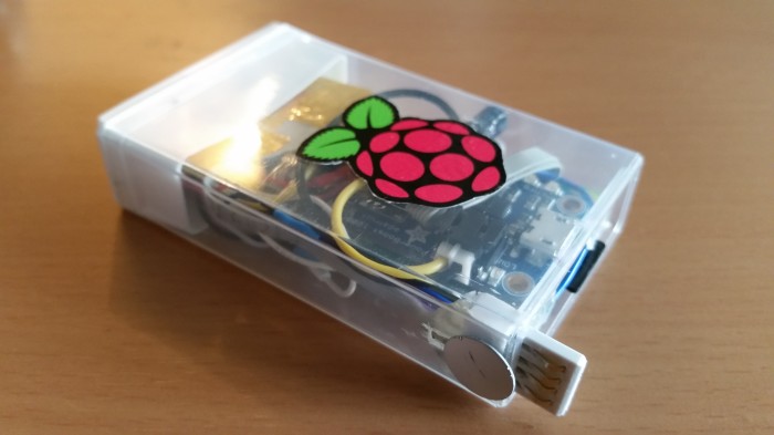
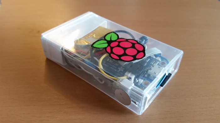
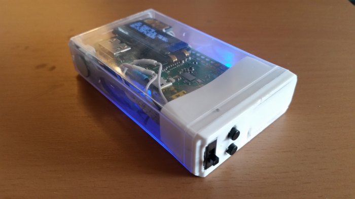
Photos:

Great project. When I was in college a long, long time ago, the computer that we used took up an entire floor of the business building. It was probably no more powerful that the one you fit in a Tic Tac box.
Thanks for sharing.
LikeLiked by 1 person
[…] 07:12 = Pi-Tac: Raspberry Pi Zero W in Tic-Tac Box · [link] […]
LikeLiked by 1 person
[…] is probably one of the best illustration of that indisputable fact that I’ve ever seen. The setup stuffs not solely a Pi Zero W right into a Tic Tac field, but additionally the entire supporting […]
LikeLike
[…] is probably the very best illustration of that incontrovertible fact that I’ve ever seen. The setup stuffs not solely a Pi Zero W right into a Tic Tac field, but additionally the entire supporting […]
LikeLike
[…] probably the most effective illustration of that incontrovertible fact that I’ve ever seen. The setup stuffs not solely a Pi Zero W right into a Tic Tac field, but additionally all the supporting electronics […]
LikeLike
[…] is maybe the perfect illustration of that incontrovertible fact that I’ve ever seen. The setup stuffs not solely a Pi Zero W right into a Tic Tac field, but in addition the entire supporting […]
LikeLike